You're viewing free preview questions — 5 questions previewing here — subscribe to unlock 137 more, plus the Full Question Bank, Mock Papers & Worksheets.Upgrade
Series and Parallel Circuits — Free MYP4 Physics Practice Questions

1QuestionElectrical Components and their symbolsConcept Practice
2 marks~3 minCriterion D
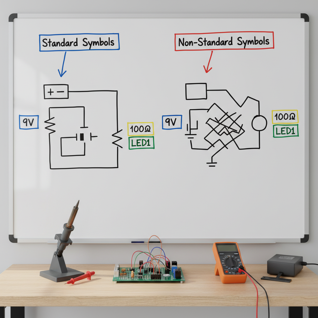
In the global electronics industry, engineers in different countries routinely share circuit schematics to manufacture and assemble devices.
a
Identify one real-world context in the electronics industry where standardized electrical symbols are essential. [1]
b
Explain one consequence that could arise if electrical symbols were not standardized across countries. [1]

Solutions
2QuestionCurrent and Voltage in Parallel CircuitsAssessment Practice
4 marks~6 minCriterion B
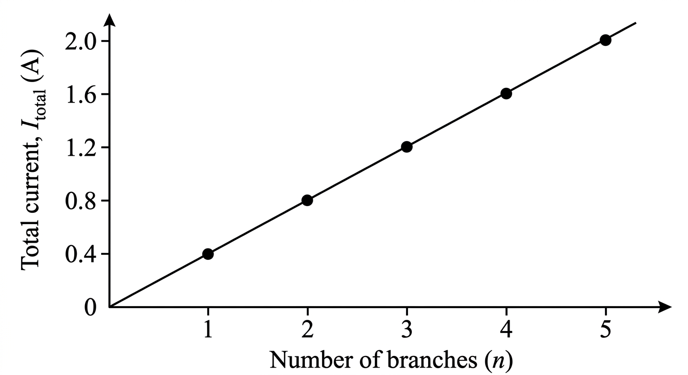
A student builds a parallel circuit at a constant supply voltage of 6.0 V. Each branch contains an identical resistor of 15 Ω. The student adds branches one at a time and records the total current.
a
Interpret the pattern shown in the graph between the number of branches and the total current. [1]
b
Deduce the total current when 4 branches are connected. Show your reasoning. [1]
c
Analyse the relationship between total resistance and number of branches. Justify whether this relationship is linear or non-linear, and explain what this means for how resistance changes as the circuit grows. [2]
Solutions
3QuestionElectrical Components and their symbolsConcept Practice
3 marks~5 minCriterion A
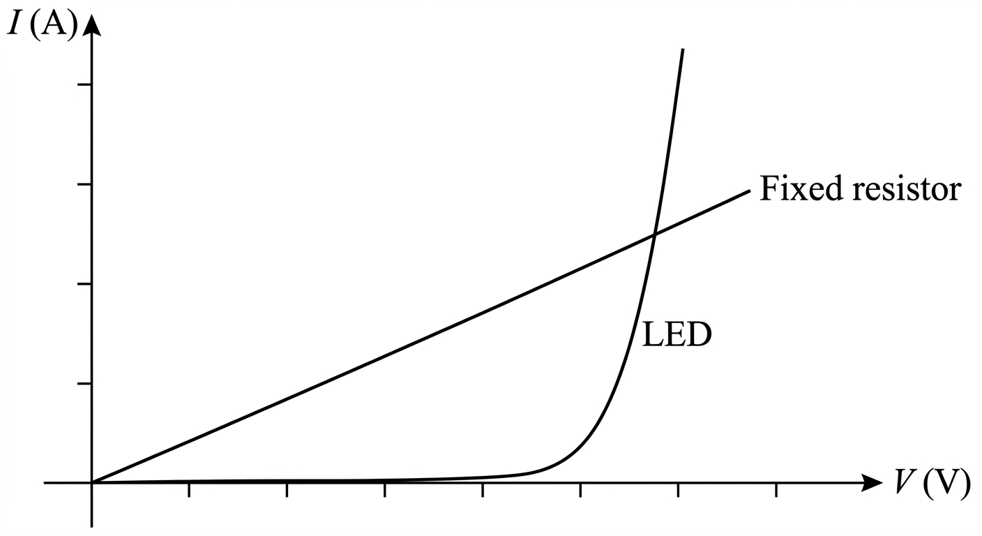
The graph below shows the current–voltage (–) characteristics of a fixed resistor and an LED. The fixed resistor produces a straight line through the origin; the LED produces a curve that rises slowly at first, then steeply beyond a threshold voltage.
a
State Ohm's Law and write its mathematical form. [1]
b
Explain why the fixed resistor obeys Ohm's Law, with reference to the shape of its – graph. [1]
c
Explain why the LED does not obey Ohm's Law, referring to both the shape of its – graph and what this reveals about its resistance. [1]
Solutions
4QuestionConstructing Simple Electrical CircuitsAssessment Practice
5 marks~8 minCriterion A
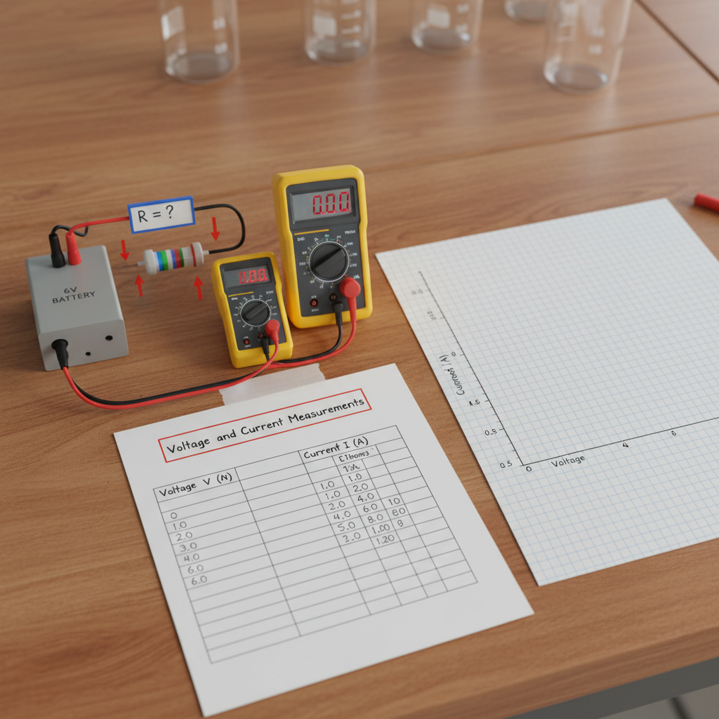
A student builds a circuit to investigate an unknown resistor, measuring current for different voltages . The results are shown below.
(V): 0, 1.0, 2.0, 3.0, 4.0, 5.0, 6.0
(A): 0, 0.20, 0.40, 0.60, 0.80, 1.00, 1.20
A straight line of best fit is drawn through the origin on an – graph.
(V): 0, 1.0, 2.0, 3.0, 4.0, 5.0, 6.0
(A): 0, 0.20, 0.40, 0.60, 0.80, 1.00, 1.20
A straight line of best fit is drawn through the origin on an – graph.
a
Deduce the resistance of the unknown resistor using the gradient of the – graph. [2]
b
Explain why the gradient of an – graph equals , rather than itself. [1]
c
The resistor is now connected in series with an identical second resistor. Analyse how this change affects the gradient of the – graph and the current at V. [2]
Solutions
5QuestionConstructing Simple Electrical CircuitsAssessment Practice
8 marks~12 minCriterion D
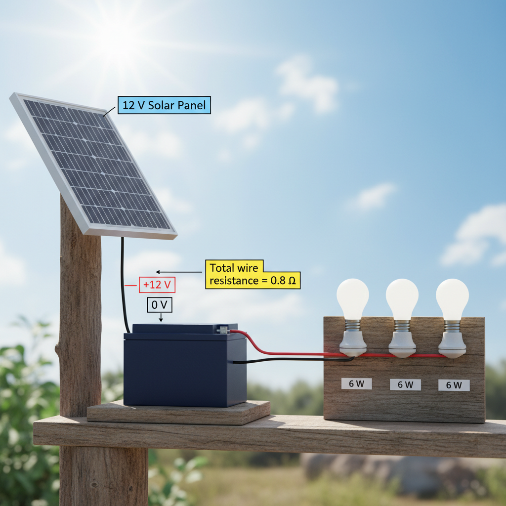
A non-profit organisation installs solar home systems in a rural off-grid community. Each system uses a 12 V battery and three 12 V LED bulbs, each rated at 6 W, connected in parallel. The total wire resistance between the battery and the bulbs is 0.8 Ω. Assume the bulbs behave as ohmic resistors.
a
Calculate the total current drawn from the battery and the voltage drop across the wires. Use and . [2]
b
Explain how this voltage drop affects the power delivered to the bulbs and the energy efficiency of the system. [2]
c
The organisation chose thin, high-resistance wires to reduce upfront costs for low-income households. Discuss the ethical trade-off between affordability and system reliability, and analyse how poor performance may affect long-term community trust in off-grid solar technology. [3]
d
Justify one design change that would improve system performance without making the system unaffordable. [1]
Solutions
That's every free question here — 5 of 142.
+137 more questions, plus Mock Papers & Worksheets, are waiting in Premium.