You're viewing free preview questions — 5 questions previewing here — subscribe to unlock 160 more, plus the Full Question Bank, Mock Papers & Worksheets.Upgrade
Reflection and Refraction of Light — Free MYP4 Physics Practice Questions

1QuestionPlane Concave and Convex MirrorsConcept Practice
2 marks~3 minCriterion C
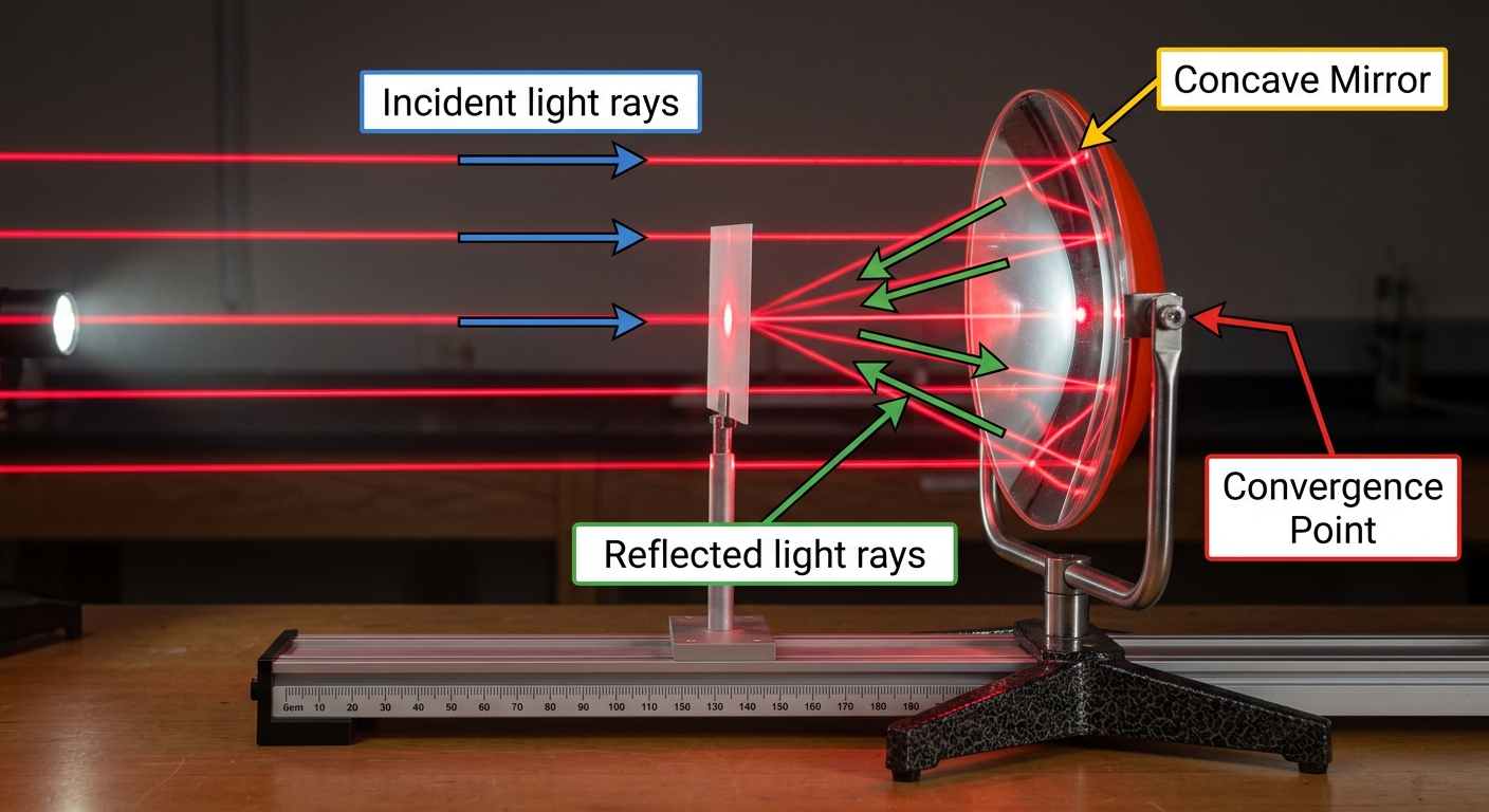
The diagram shows parallel rays of light striking a concave mirror. After reflection, the rays pass through a single point on the principal axis.
a
Identify the type of mirror shown. [1]
b
Explain why parallel rays incident on this mirror converge at one specific point rather than being reflected in random directions. [1]

Solutions
2QuestionRay Diagrams and Image Formation BasicsAssessment Practice
5 marks~8 minCriterion A
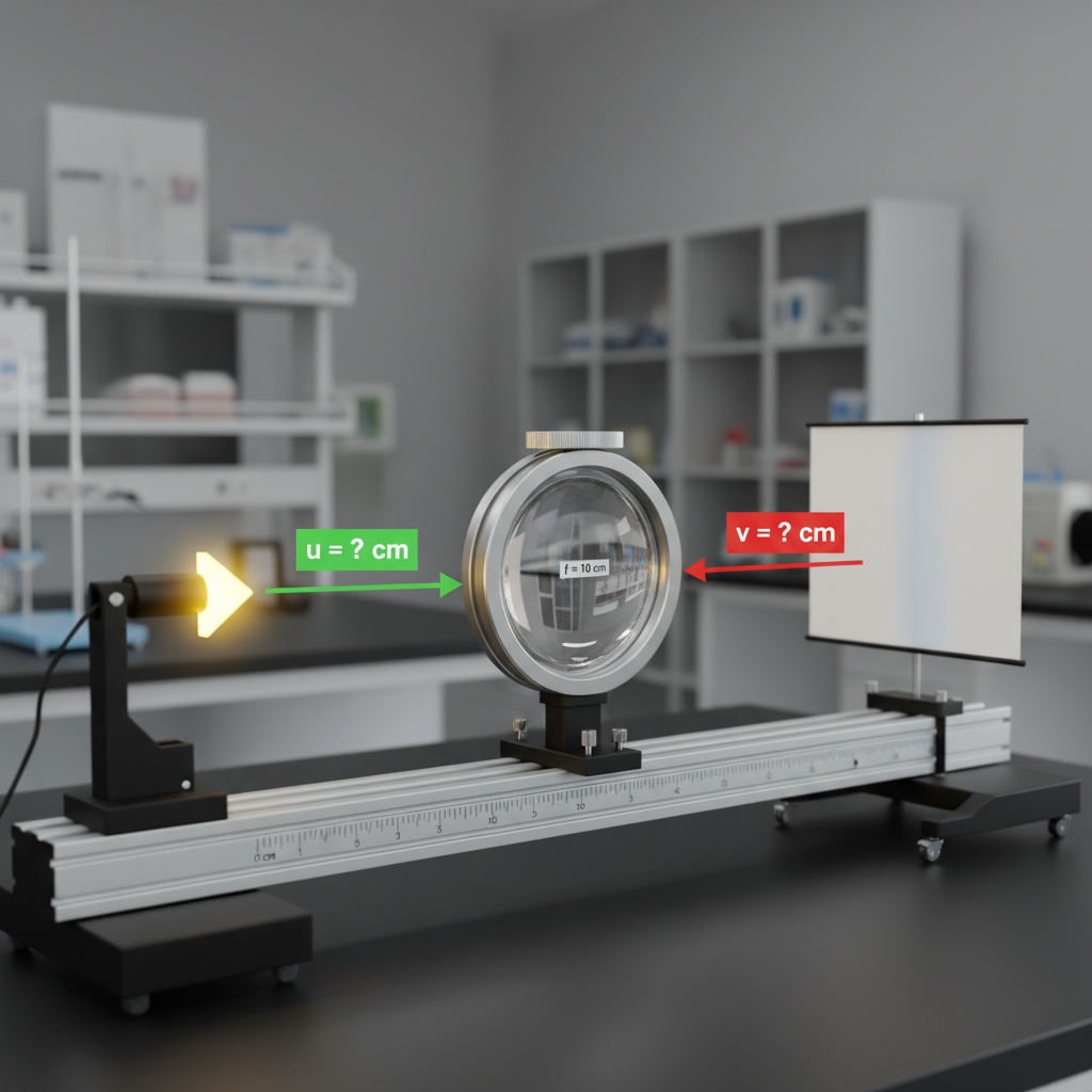
A student investigates image formation by a converging lens of focal length cm. She places an object at distances from the lens and records the image distance .
(cm): 20.0, 15.0, 12.0, 10.0, 5.0
(cm): 20.0, 30.0, 60.0, undefined, −10.0
(cm): 20.0, 15.0, 12.0, 10.0, 5.0
(cm): 20.0, 30.0, 60.0, undefined, −10.0
a
Describe the pattern relating to as decreases from 20.0 cm to 5.0 cm. Include reference to the sign of . [2]
b
Using the lens equation , deduce the value of when cm, and justify what the sign of your answer indicates about the image. [3]
Solutions
3QuestionLenses Converging and Diverging IntroductoryConcept Practice
2 marks~3 minCriterion A
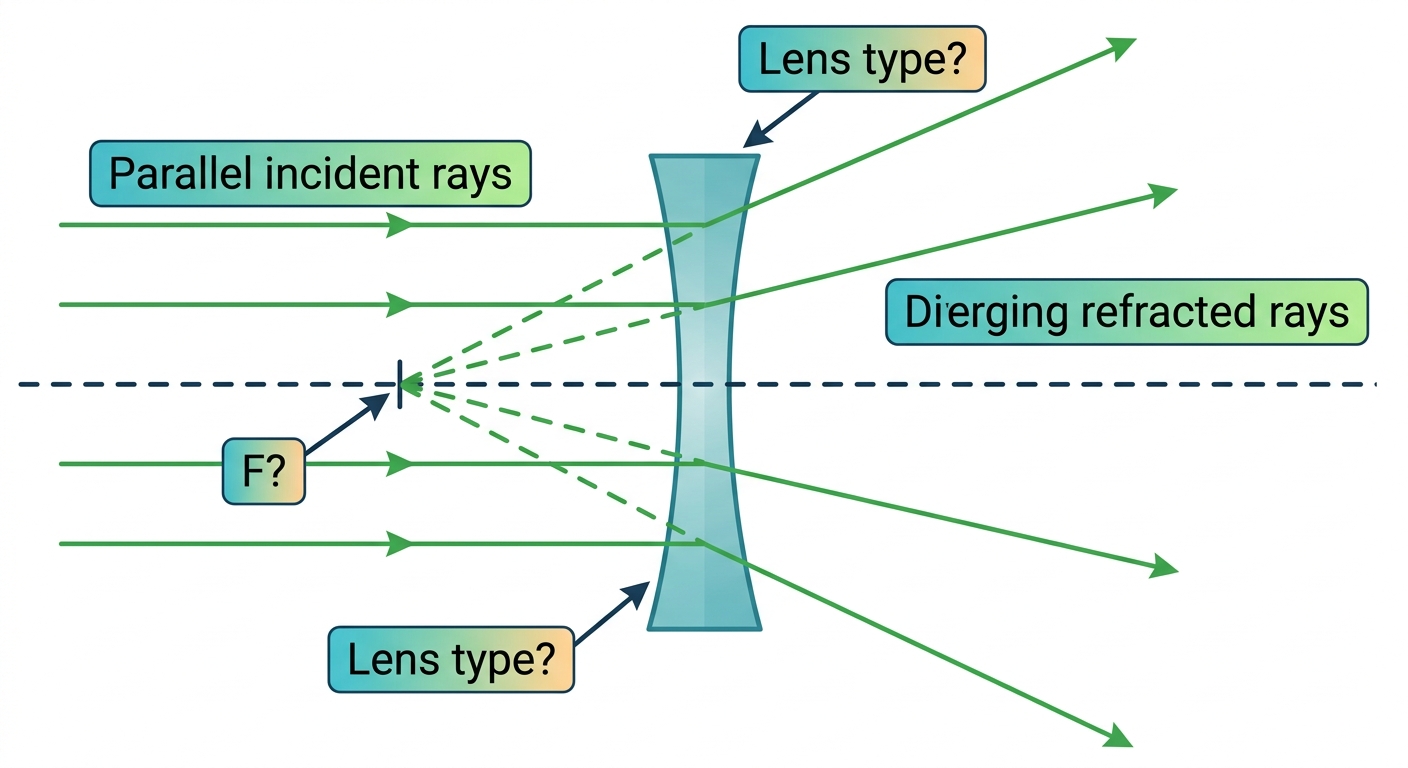
A ray diagram shows three parallel rays of light entering a lens. After passing through the lens, the rays diverge. When extended backwards, the diverging rays appear to meet at a single point on the same side of the lens as the incoming rays.
a
Identify the type of lens shown and explain how the behaviour of the rays supports your answer. [1]
b
Deduce the name given to the point at which the extended rays appear to meet, and state whether this point is real or virtual. [1]
Solutions
4QuestionPlane Concave and Convex MirrorsAssessment Practice
6 marks~9 minCriterion B
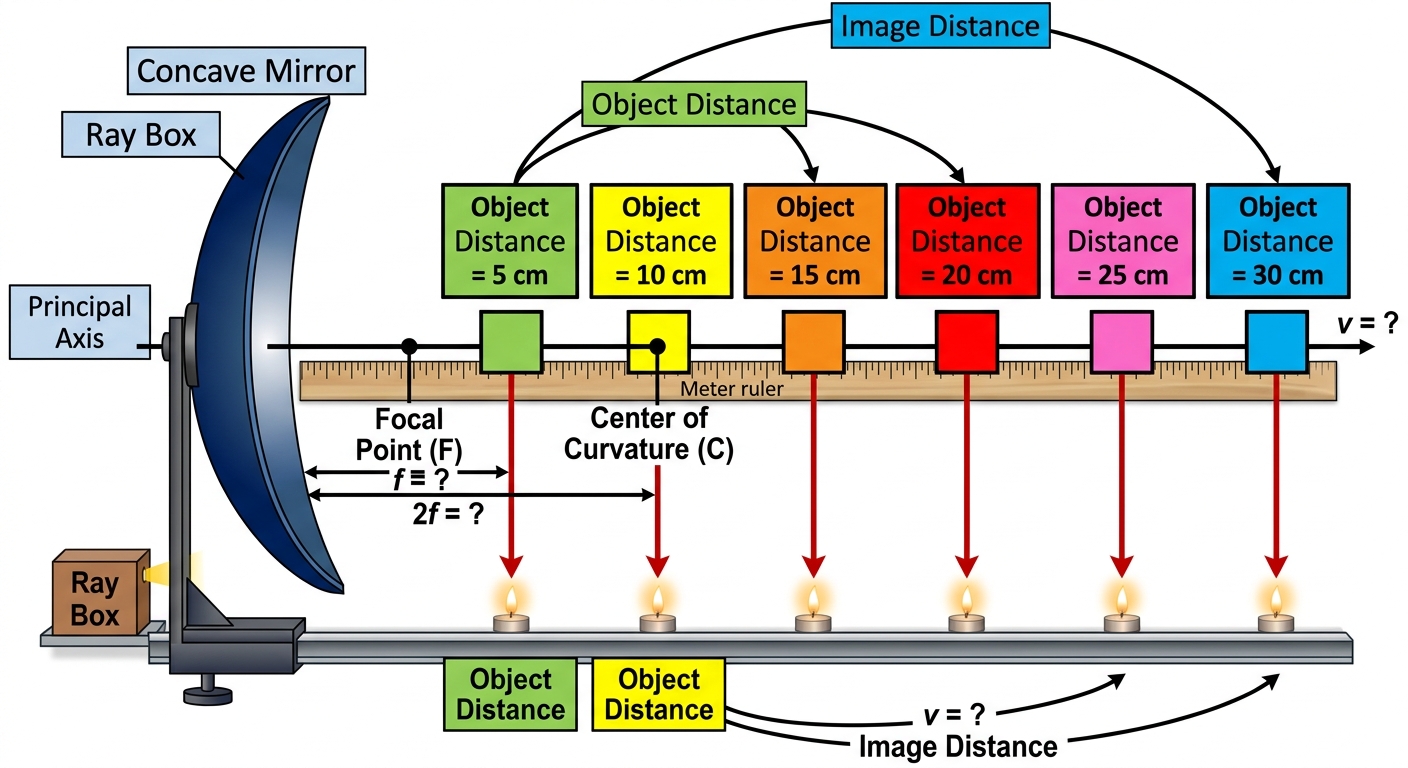
A student investigates a concave mirror of unknown focal length , where , by placing an object at distances 5, 10, 15, 20, 25, and 30 cm and recording the image formed at each position.
a
Predict the image characteristics (real/virtual, upright/inverted, magnified/diminished) at each of the six object distances. [2]
b
Using your predictions, deduce a general rule that relates the type of image produced to the object's position relative to and . [2]
c
Justify your rule in part (b) by discussing the behaviour of principal rays in a concave mirror ray diagram, including what happens when reflected rays diverge rather than converge. [2]
Solutions
5QuestionRefraction Through Glass Blocks and WaterAssessment Practice
8 marks~12 minCriterion D
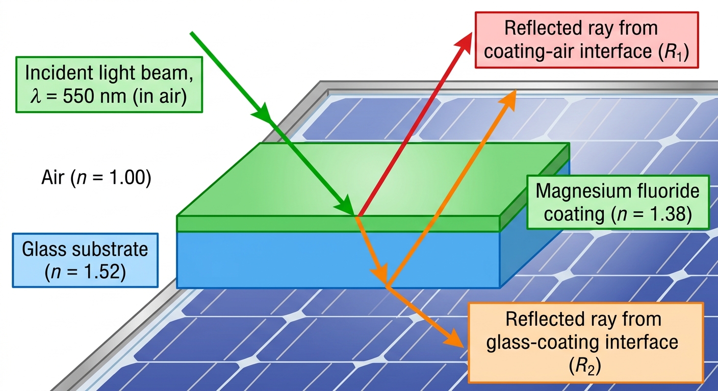
Anti-reflective coatings on solar panels use thin-film interference to reduce reflection losses. A magnesium fluoride layer () is deposited on a glass substrate (). Manufacturing requires rare materials — lanthanum and hafnium — sourced from limited locations, causing environmental disruption. After 25–30 years, separating coating layers from the glass substrate during recycling is difficult. A solar panel operates in a location receiving peak sun hours per day.
Use , where is energy in kWh, is power in kW, and is time in hours.
Use , where is energy in kWh, is power in kW, and is time in hours.
a
Explain how the magnesium fluoride coating reduces reflection of light with wavelength in air. State the condition for destructive interference in terms of coating thickness , wavelength , and refractive index . [2]
b
The coating increases the panel's power output by . Calculate the additional electrical energy generated per year, assuming the panel operates for 365 days. Show your working clearly. [2]
c
Evaluate the trade-offs involved in using advanced anti-reflective coatings on solar panels. In your response, address at least two of the following: environmental cost of mining and manufacturing; benefits of increased renewable energy generation; challenges of recycling and disposal; unequal global distribution of critical materials. Also discuss one limitation of the thin-film interference model in predicting coating performance over the panel's lifetime. [4]
Solutions
That's every free question here — 5 of 165.
+160 more questions, plus Mock Papers & Worksheets, are waiting in Premium.