
Electricity and Magnetism: MYP 3 Revision Teaser
Series vs parallel circuits, resistance, conductors, and magnets — the five ideas examiners test most.
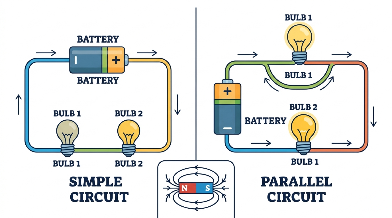
Quick facts
Electricity and magnetism in MYP Year 3 comes down to four connected ideas: how charge moves through a circuit, what lets it move or stops it, how moving charge makes a magnetic field, and how that links to permanent magnets. Series and parallel circuits are the single most repeated question type — expect a calculation using paired with an explanation of ammeter or voltmeter readings. Conductors and insulators come down to whether electrons are free to move, while magnets always come in N–S pairs, mapped by field lines running from north to south. This teaser pulls out the five concepts worth locking down first, including the exact traps examiners set with 'explain' questions. For full worked examples, diagrams, and every definition, the complete MYP 3 revision notes on RevisionPrep go much deeper than this summary.
What you’ll be able to do
Series vs Parallel Circuits: The Exam's Favourite Question
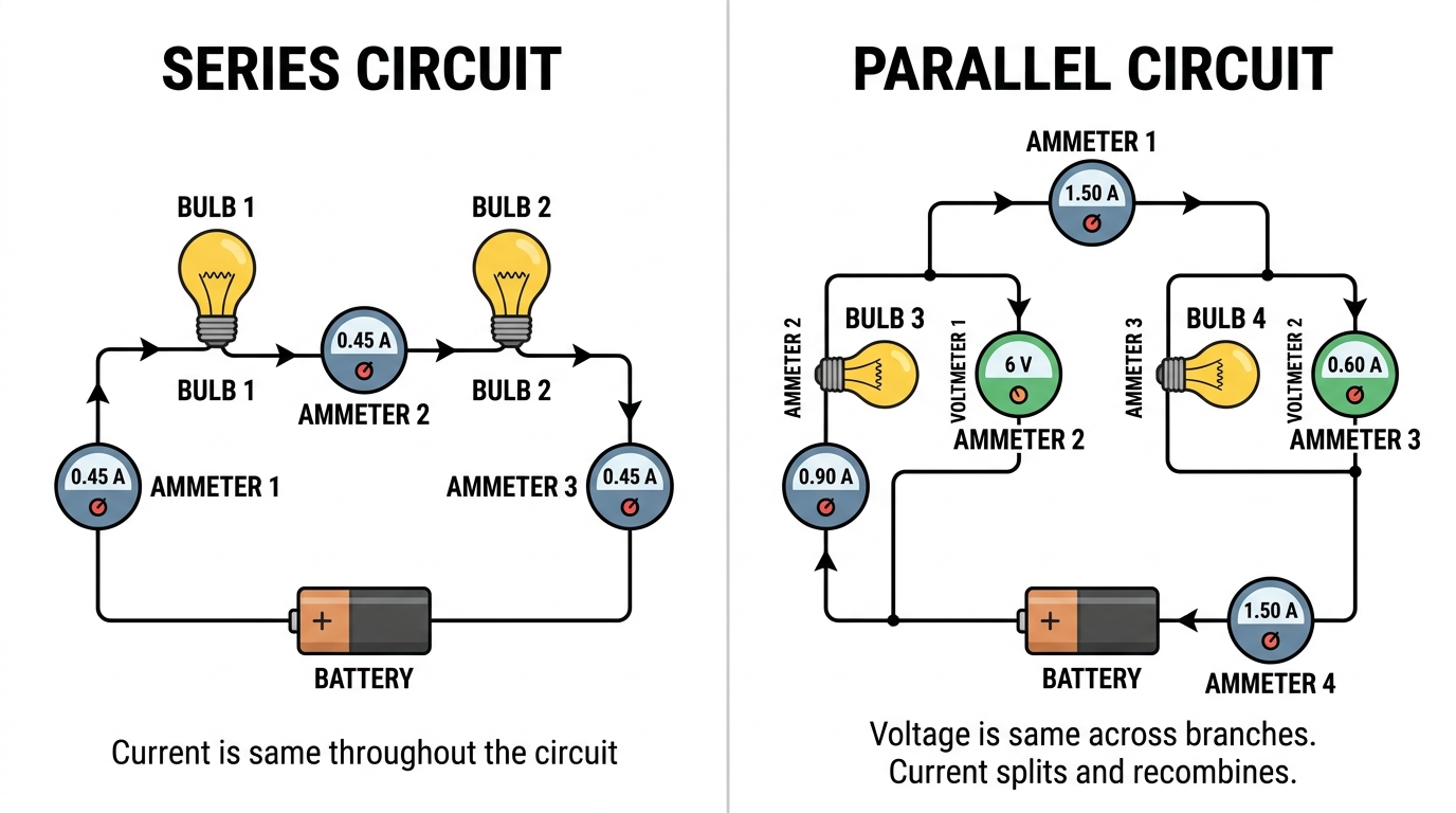
A series circuit gives current only one path, so the same current flows through every component and the supply voltage gets shared out between them. A parallel circuit gives current a choice at every junction — voltage stays equal across each branch, but current splits between branches and recombines back to the original total. Adding a bulb in series makes every bulb dimmer and breaks the whole circuit if one blows; adding a bulb in parallel keeps every bulb at full brightness and lets the others keep working if one fails.
| Feature | Series circuit | Parallel circuit |
|---|---|---|
| Current | Same everywhere | Splits between branches, recombines at junctions |
| Voltage | Shared between components | Same across every branch |
| If one bulb blows | Whole circuit stops | Other bulbs keep working |
Exam tip
Use the precise vocabulary the mark scheme wants: 'path' for series (only one) and 'branch' for parallel (multiple). Saying 'parallel has more wires' can lose the mark even if your idea is right.
Common mistake
Seeing ammeter readings like 0.24 A, 0.23 A, 0.25 A at three points in a series loop and concluding current decreases. In reality, current is identical at every point in a single loop — those small differences sit within the ammeter's uncertainty (±0.01 A), and it's energy, not current, that gets used up by each bulb.
Mini summary
Series = one path, same current, shared voltage. Parallel = multiple branches, same voltage, split current.
Calculating Resistance with $R = V/I$
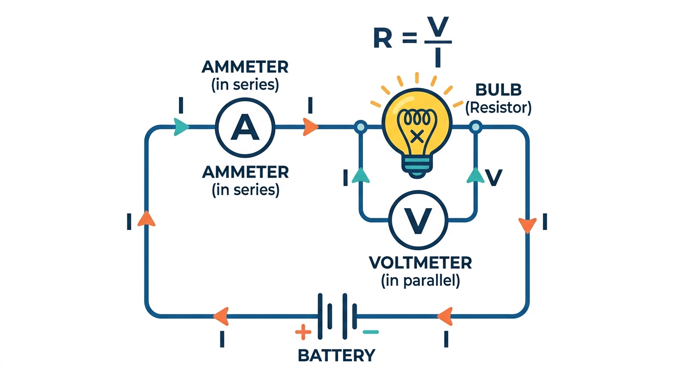
Resistance measures how much a component opposes current, and it's calculated with , where V and I must belong to the same thing — either one component or the whole circuit, never mixed. In series, total resistance is just the sum of every resistor: . In parallel, total resistance uses reciprocals: , which always gives a smaller total than any single branch.
Exam tip
Never divide one bulb's voltage by the circuit's total current, or vice versa. Match V and I to the same object before you divide — this is the single most common calculation trap.
Mini summary
only works when voltage and current match the same component or the same whole circuit.
Conductors and Insulators: Why Some Materials Carry Current
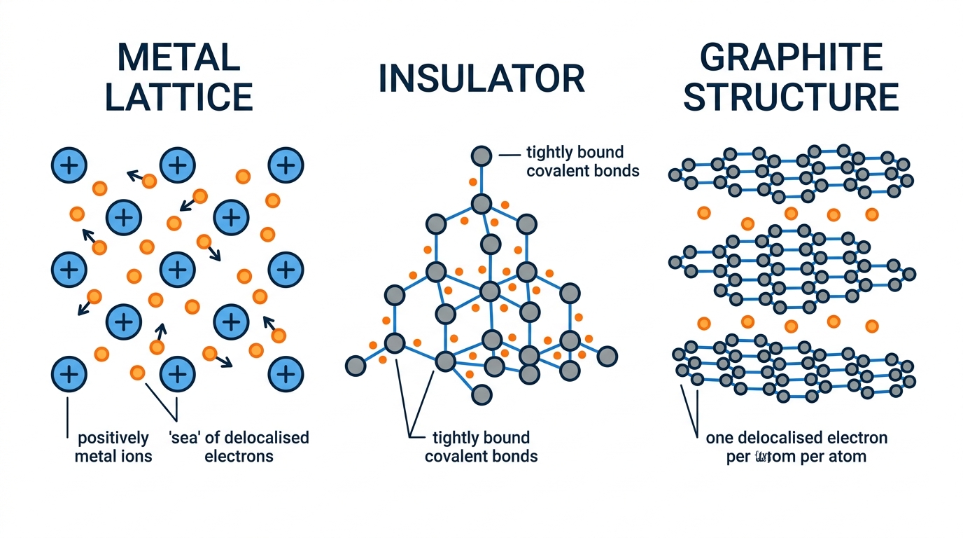
Whether a material conducts depends on whether it has free charge carriers. Metals have a 'sea' of delocalised electrons that drift through the structure under a voltage, making them good conductors — copper is the everyday choice for wiring because it's far cheaper than silver, even though silver conducts slightly better. Most non-metals hold their electrons tightly in covalent bonds and insulate, except graphite, which conducts because each carbon atom leaves one electron delocalised between its layers.
| Material | Conductor or insulator | Why |
|---|---|---|
| Copper | Conductor | Delocalised electrons, cheap for wiring |
| Rubber/PVC | Insulator | Electrons bound tightly in covalent bonds |
| Graphite | Conductor | One delocalised electron per carbon atom between layers |
Exam tip
'Copper is a conductor' states a fact. 'Explain why copper conducts' needs the mechanism — free/delocalised electrons that move under a voltage. Explain questions always need that extra causal sentence.
Common mistake
Saying insulators 'never' conduct. In reality they don't conduct at everyday voltages, but a large enough voltage can force electrons through — exactly what happens when lightning breaks down air.
Magnets, Poles and Magnetic Field Lines
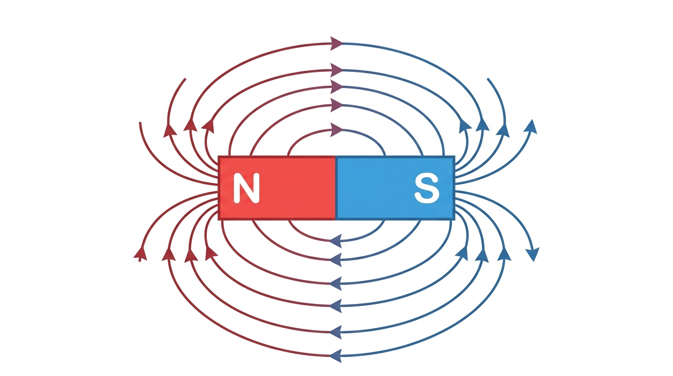
Every magnet has a North and South pole, and you can never isolate just one — cutting a bar magnet in half always produces two smaller magnets, each with its own N and S. Like poles repel and unlike poles attract, and the magnetic field around a magnet is mapped with field lines that run from N to S outside the magnet, then continue from S back to N inside it, forming closed loops. Field lines bunch closest together at the poles, which is exactly where the field is strongest.
Mini summary
Poles always come in N–S pairs; field lines run N to S outside the magnet and loop back inside.
Answering 'Explain' Questions Without Losing Marks
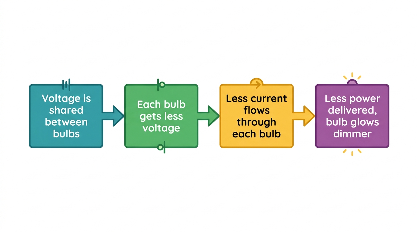
Command term 'Explain' always needs a causal mechanism, not just a restated observation — 'they share the voltage' earns nothing until you connect reduced voltage to reduced current and then to reduced brightness or power. This same principle applies across the whole topic: stating 'copper conducts' or 'ammeter readings differ slightly' isn't enough without the 'because' clause that examiners are scoring for.
Exam tip
Build every explain answer as a chain: observation → because → mechanism → effect. For dimmer bulbs in series: voltage is shared, so each bulb gets less voltage, so less current flows, so less power is delivered, so the bulb glows dimmer.
Common mistake
Stopping at 'the bulbs share the voltage' without linking that reduction all the way through to reduced brightness — this loses the explain mark even though the starting idea is correct.
Quick formula sheet
Practice questions
- State one difference between how current behaves in a series circuit compared to a parallel circuit.
- Name two good electrical conductors and two good electrical insulators.
- State what happens when the North pole of one magnet is brought near the North pole of another.
- Two identical bulbs are wired in series across a 6 V battery. If each bulb reads 3 V, calculate the resistance of one bulb given the current is 0.3 A.
- Explain why graphite conducts electricity even though it is a non-metal.
- Explain why bulbs in a parallel circuit stay lit even if one bulb blows, but bulbs in a series circuit all go out.
- Three ammeter readings around a single series loop are 0.24 A, 0.23 A and 0.25 A. Explain why this does NOT mean current is decreasing as it flows around the circuit.
- A parallel circuit has two branches carrying 0.6 A each from a source. Explain, using the idea of charge conservation at a junction, what the total current leaving the battery must be.
- Explain why cutting a bar magnet in half never produces a magnet with only one pole.
Frequently asked questions
What is the main difference between series and parallel circuits?+
In series, current has only one path and is the same everywhere, while voltage is shared between components. In parallel, voltage is the same across every branch, while current splits between branches and recombines at junctions.
Why do bulbs glow dimmer when wired in series?+
The supply voltage gets shared between the bulbs, so each bulb receives less voltage, which reduces the current through it and the power it delivers, making it glow dimmer.
Why is copper used for wiring instead of silver, which conducts better?+
Silver conducts slightly better than copper, but copper is used because it is far cheaper while still having free delocalised electrons that carry current effectively.
Why can't insulators conduct electricity?+
Insulators hold their electrons tightly in covalent bonds, so there are no free charge carriers at normal voltages. A large enough voltage, like a lightning strike, can still force electrons through.
Why can't a magnet have just one pole?+
Cutting a magnet in half always produces two smaller magnets, each with its own North and South pole — an isolated single pole does not exist.
Why do ammeter readings around a series circuit sometimes look slightly different?+
Current is actually identical at every point in a single-loop series circuit. Small differences in readings come from the ammeter's measurement uncertainty, not from current being used up.
Master Electricity and Magnetism with the full MYP 3 revision notes
Related articles