
Physics: Circuit Continuity: Series Circuits and Current Flow
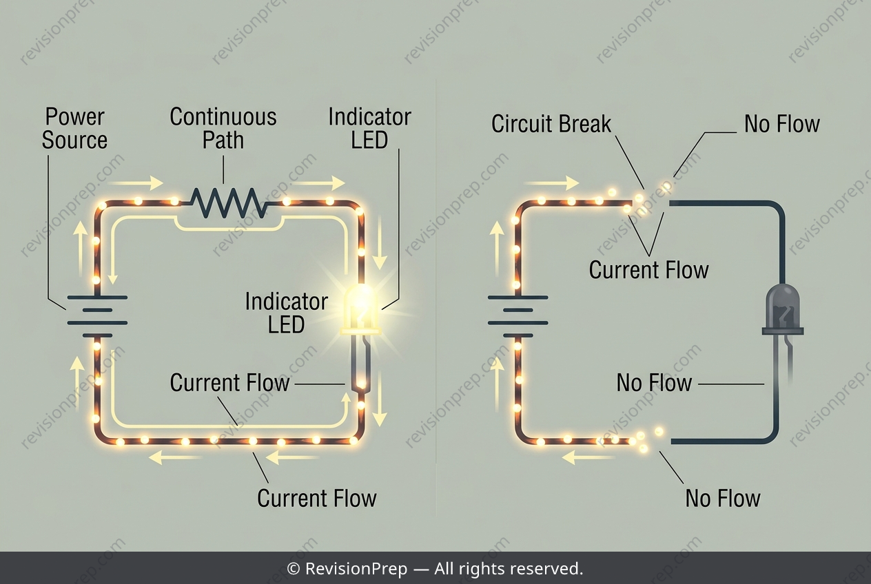
In a series circuit, components are connected end-to-end, forming a single, unbroken pathway for electric charge to flow. The defining rule is that the current (I) is identical at every point in the loop, and the total resistance (Rtotal) is simply the sum of all individual resistances (Rtotal = R₁ + R₂ + R₃ + ...). This arrangement creates a strict dependency: if any single component fails or a connection breaks, the entire circuit becomes open, and current flow stops everywhere simultaneously. This fundamental principle is the backbone of circuit diagnostics, particularly in tools like a continuity tester. Here, a battery, a resistor, an LED, and the wire under test are all linked in series. The LED lights only when the wire is intact, providing a complete conducting path. Because there is only one route for current, a break in the wire acts like a switch turned off—it interrupts the flow at that point, preventing any charge from reaching the LED. This binary on/off response directly reveals the wire’s continuity. However, this simplicity also highlights a key limitation: the tester cannot distinguish between a perfect connection and a high-resistance fault, like a corroded joint, which still allows a small, insufficient current to flow.
Start practising IB questions today
150,000+ IB-styled questions, criteria-mapped and instantly accessible.